Privacy statement: Your privacy is very important to Us. Our company promises not to disclose your personal information to any external company with out your explicit permission.
0 Preface
Since the 1990s, optical communication has developed rapidly due to its frequency bandwidth, large capacity, strong anti-interference and strong confidentiality. It plays an increasingly important role in the field of national defense and daily communication. Infrared light is not light. Seeing the scope, it has strong anti-interference ability and is not easy to be captured, so infrared communication has high research value.
The system design uses infrared pair tube as the transceiver device, and uses TDA2822M integrated operational amplifier and peripheral components to form the transmitting circuit and receiving circuit and perform modulation, demodulation and power amplification. The whole system is stable and reliable. With the change of transmission distance, the change of its signal strength can be monitored in real time.
1. Basic principles and design
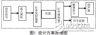
The infrared light of the 950 nm near-infrared band is used as the medium for transmitting information, and the natural space is used as the communication channel. The transmitting system uses the electric signal to convert and amplify and modulate, and drives the infrared transmitting tube to emit the optical signal with the infrared light as the carrier. The infrared light signal is wirelessly transmitted through the space to the receiving end. After receiving the infrared light signal, the receiving end demodulates, amplifies, filters, and so on, and then sends it to the output end to implement the communication process. A monitoring circuit is used to monitor the signal. The principle of its design is shown in Figure 1.

2. Circuit design
2.1 Transmitter circuit
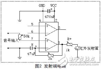
A two-channel integrated operational amplifier TDA2822M and peripheral components infrared light-emitting tube, capacitor, fixed resistor, precision adjustable resistor and 6V DC power supply constitute a modulation transmitter circuit shown in Figure 2.

2.2 Receiver circuit
Similarly, the TDA2822M integrated operational amplifier is used, and the peripheral components 9014 triode, fixed resistor, precision adjustable resistor, capacitor, infrared receiving tube, speaker and 6V DC power supply form a demodulation receiving circuit. When the modulated light is incident on the infrared receiving tube, the input optical signal is output after demodulation and amplification, and the audio signal is outputted in the speaker; the transmitting end and the receiving end independently use a 6V DC power supply to eliminate interference to the circuit system. See Figure 3.

2.3 signal monitoring circuit
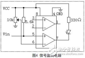
Using a voltage comparator LM393, the receiving end takes the signal out and sends it to the comparison circuit. Compared with the reference voltage set at the 6th pin, the LED is driven by the compared output voltage. When the receiving LED is not illuminated, the opposite is true. When the receiving end receives the signal, the LED is not lit; thus implementing the monitoring circuit. See Figure 4.

May 10, 2024
April 18, 2024
January 13, 2024
January 13, 2024
January 10, 2024
この仕入先にメール
May 10, 2024
April 18, 2024
January 13, 2024
January 13, 2024
January 10, 2024

Privacy statement: Your privacy is very important to Us. Our company promises not to disclose your personal information to any external company with out your explicit permission.

Fill in more information so that we can get in touch with you faster
Privacy statement: Your privacy is very important to Us. Our company promises not to disclose your personal information to any external company with out your explicit permission.